Building a Wifi controlled bot using Nodemcu and l293d motor driver ic
For this project we need a l293d motor driver ic, a breadboard, some jumper cables,nodemcu(esp8266),a five volt power supply(or i can just use arduino for the 5v power supply as that 5v is not present on nodemcu),a 9v supply to run the motor.
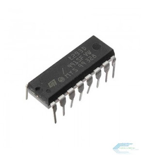
L293D
CHASIS FOR THE BOT
NODEMCU(ESP8266)
JUMPER CABLES
L293D
CHASIS FOR THE BOT
NODEMCU(ESP8266)
JUMPER CABLES
ARDUINO(I HAVE USED FOR 5V POWER SUPPLY)
NODEMCU(ESP8266)
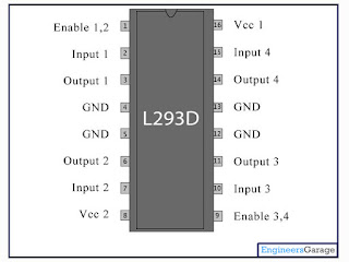
THE IC HAS 4 INPUT PINS ,4 OUTPUT PINS,4 GND PINS,TWO ENABLE PINS AND TWO Vcc.
The output pins are connected to the motors .Two outputs on each motor.
The input comes from the digital pins of the nodemcu.
If you connect 5v to the enable 1,2 then all the pins on the left will be activated and connecting 5v with enable 3,4 then all pins on the right get activated.
now discussing about ground pins. All ground pins are sorted with each other.then one terminal is connected to the ground terminal of the arduino or node mcu.
next the Vcc2 is connected to the 9v supply. Vcc2 is used as the motor driving voltage.
and Vcc1 is connected to the 5v pin of arduino.Vcc1 is the Vcc of the ic.
the output 1 and output 2 on the left will be connected to a motor. And output 3 and output 4 will be connected to the another motor.
then what u need to do is just to identify the pins connected to motor and use them properly in the programming.
now going to the code


Comments
Post a Comment